Brake Control Unit (BCU)
Dual Channel Brake Control Unit
Characteristics
- Standalone Brake by Wire Control Unit for Part-25 transport aircraft
- DAL A Certifiable Development
- Two completely segregated channels in one enclosure
- Dissimilar COM/MON Safety Architecture
- DO160g Qualified (for typical avionics rack environment)
The BCU is a typical standalone Brake Control Unit for a two channel inboard/outboard hydraulic Brake-by-Wire System of a medium sized turboprop Part-25 aircraft.
BCU Functions
Control Functions
- Normal Brake Control
- Autobrake
- De-spin
- Antiskid Functions
-
- Touch Down protection
-
- Locked wheel protection
-
- Skid control
- Ground spoiler deployment
Monitoring Functions
- Brake temperature monitoring
- Built-in-Test
-
Uncommanded brake monitoring
Top Level Architecture
The BCU consists of two completely independant and segregated channels controlling the inboard and outboard wheels respectively. The two channels are separated by a solid aluminum sheet to prevent propagation electrical faults.
Each channel provides two lanes,
the COMmand lane and the
MONitor lane. The
COM lane acquires and validates the pilot commands (via pedals,
autobrake selector, etc.), and controls the brakes via Brake Control
Servo Valve. It performs autobrake, de-spin braking as well as antiskid
functions.
The MON lane is protecting against uncommanding braking
at high speed. (the only catastrophic failure condition needing
dissimilar monitoring).
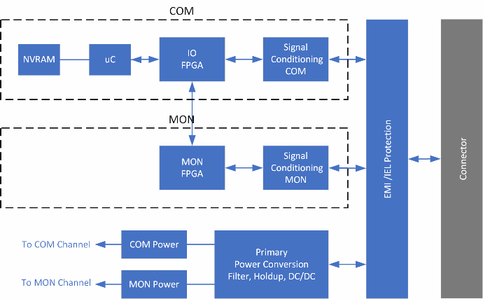
The COM Lane consist of a
microcontroller implementing the higher level functions, an FPGA
implementing the I/O functions, signal conditioning and
power conversion. The MON lane consist of an FPGA, signal condioning and
power conversion. The FPGA is implementing I/O as well as the
uncommanded braking monitoring functions.
The FPGAs COM and MON lanes as well as all other circuits which can lead to erroneous behavior are dissimilar.
The top level COM / MON architecture for one channel is shown below:
Environmental Qualification
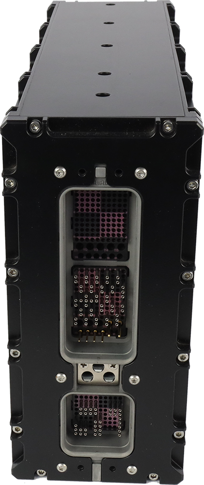
The BCU is built into a 3MCU ARINC600 Housing. All sides of the housing are manufactured milled aluminum sheet, optimized for low weight at sufficient stiffness.
BCU is qualified according to RTCA / DO 160G.
Technical Data
Interfaces per Channel
-
4 x LVDT Inputs for Brake Pedal Sensors
- 8 x Discrete Inputs for Autobrake Selector and Landing Gear
-
2 x Analog outputs for Brake Control Servo Valve
- 2 x Solenoid Control Outputs for ShutOff Valve
- 2 x Pressure Sensor Acquisition
- 2 x Wheel Speed Sensor Acquisition
-
2 x Brake Temperature Acquisition
- 2 x ARINC 429 TX
- 2 x RS422
Power Input and Consumption
- Input power: 28VDC
-
Dual Power Supply for Inboard and Outboard channel
- Power consumption < 10W
Weight & Physical Dimensions
- 3.2 kg
- 319.5 x 194 x 90 mm
External Connectors
- ARINC 600 Size 2
Availability
- 41.000 FH
Customization
- BCU variants can be provided with different number / type of I/O interfaces within certain limits.