System Level Integration with ADS
2
/ SIB - HLSIR
System Integration Bench for MA700 High Lift System
Overview
To fully integrate the Control (sub)System and Actuation (sub)System of MA700 HLS, TechSAT has delivered one HLSIR (HLS Integration Rig) to QAG, the system supplier of MA700 HLS.
For the incremental IV&V approach required by ARP4754A, four levels of integration of HLS has been performed on TechSAT Test & Integration Systems.
MDVS was used to start virtual, model based development (Virtual Integration -> MA700 HLS Model Based System Level Requirements Validation)
The FECU and FMCM are each individually verified using FECUTB and FMCMTB respectively. (Equipment Level Integration -> MA700 HLS FECU Verification)
The HLS Control (sub) System, consisting of the two FECUs and two FMCMs, is verified on HLS Simulator (HLSS).
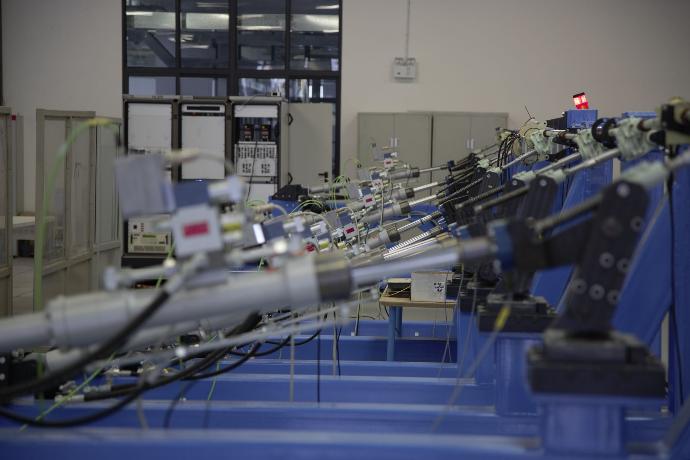
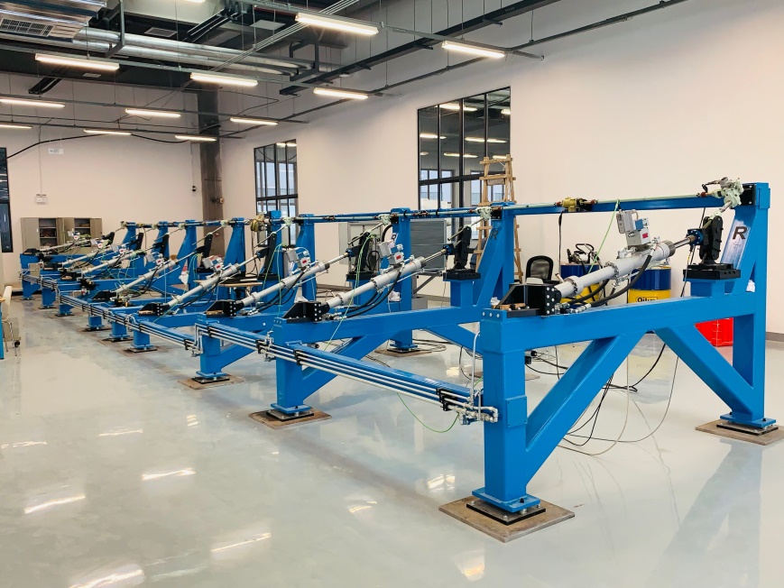
The High Lift Integration Rig (HLSIR) is used for verification and qualification of the complete High Lift System including the electronic control system, the electro-mechanical power drive, and the mechanical transmission system with shaft, torque limiter, gear boxes, and ball screw actuators.
The complete HLSIR consists of the Test & Management System (TMS) and the mechanical/hydraulic rig (RIG) as well as the integration of TMS and RIG.
System Configuration
Software Packages
- ADS2 / Core
-
ADS2 / Toolbox
- ADS2 / SCADE
- ADS2 / Simulink
-
ADS2 / FMI
- ADS2 / TPM
- ADS2 / TFG
Hardware Packages
Test & Management System
-
3x ADS2 19 Inch Racks with
-
-
Realtime High-End PC for ADS2 SW modules and Simulations
-
I/O Devices for stimulation and monitoring of the FECUs and FMCMs
-
UUT power (28VDC, 115VAC)
-
Control and monitoring interface for the hydraulic source, the load actuators and the rig instrumentation sensors
-
Wiring Matrix
-
Signal Breakout Unit
-
Special UUT Mounts
-
Mechanical Rig
- Mechanical Structure including Base structure, FBSA Load Cell, FPDU Mounts and WTB Mounts
- Hydraulic Subsystem
- Flap Load Simulation Control Loop
- Mechanical Failure Devices
- Shaft Torque Sensors
- Rig Safety Equipment
- Central Control Panel for Automated Testing & Rig Visualization
Application Logical Architecture
Logical Architecture Overview
Top Level Architecture
Use Cases
The purpose of HLSIR is to support the integration and verification of whole High Lift System.
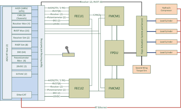
The System Under Test includes
- All Control System LRUs
-
- 1x FCL
- 1x FOS
- 2x FECU
- 2x FMCM
- Mechanical components of HLS
-
- FPDU
- Flaps actuation system for two wings
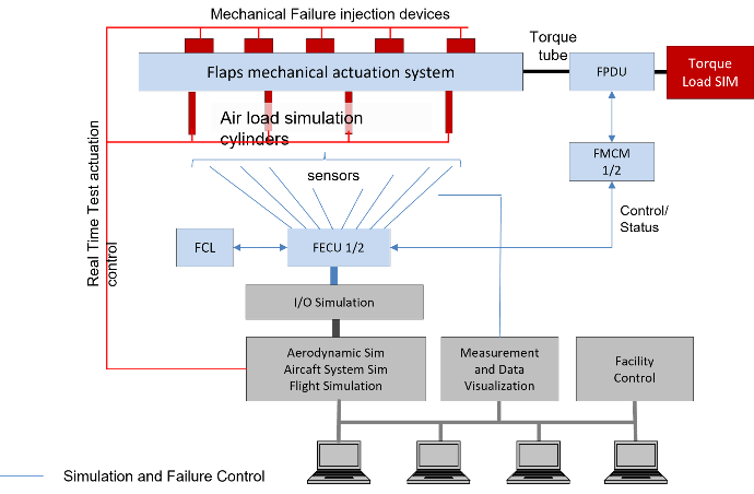
A Hydraulic Load Simulation System is integrated in HLSIR to simulate the aerodynamic forces applied to the BSA through controlled hydraulic cylinders. It uses force sensors to measure the applied force.
HLSIR provides also a Flaps Force Simulation simulating the force applied on the BSAs for the current airspeed and flaps angle and other relevant parameter.
System Level Endurance Testing
During the Endurance Testing, the HLS system is operated in normal operating mode. The full flaps cycles are continuously operated for the entire planned lifetime of HLS.
Normal Operation Mode Testing
During the Normal Operation Testing, the HLS is operated in all possible sequences from/to all positions. The position over time of HLS is verified against the expected position. The communication with external Aircraft systems, e.g. DMC is verified.
Maintenance Mode Testing
For the Maintenance Mode Testing, the HLS is set to maintenance mode at first, then the IBIT (WTB engagement, POB engagement), rigging procedure are verified. Within the maintenance mode, functions like download of configuration data and NVM are also verified.
Mechanical Failure Cases
Shaft Disconnect, FBSA Disconnect, FBSA Jam mechanical failure cases are tested on HLSIR.
Electric Failure Cases
At the system level, the loss of equipment failure cases like loss of sensors, motors, FMCM, FECU, etc. are verified.